Variable resistor for current regulation. Resistor. Resistors of variable resistance. Designation of variable resistors on the diagrams

Let's take a look at the variable resistor... What do we know about it? So far, nothing, because we still do not even know the main parameters of this very common radio component in electronics. So let's learn more about the parameters of variables and trimmers.

To begin with, it is worth noting that variables and trimmers are passive components of electronic circuits. This means that they consume energy electrical circuit in the course of their work. Passive circuit elements also include capacitors, inductors and transformers.
Parameters, with the exception of precision products that are used in military or space technology, they do not have too many:
Rated resistance. Without a doubt, this is the main parameter. The impedance can be in the range from tens of ohms to tens of megaohms. Why total resistance? This is the resistance between the extreme fixed terminals of the resistor - it does not change.
With the help of the adjusting slider, we can change the resistance between any of the extreme pins and the pin of the moving contact. The resistance will vary from zero to the full resistance of the resistor (or vice versa - depending on the connection). The nominal resistance of the resistor is indicated on its case using an alphanumeric code (M15M, 15k, etc.)
Dissipated or rated power(resistor power). In conventional electronic equipment, variable resistors are used with a power of: 0.04; 0.25; 0.5; 1.0; 2.0 watts or more.
It should be understood that wire-wound variable resistors, as a rule, are more powerful than thin-film ones. Yes, this is not surprising, because a thin conductive film can withstand much less current than a wire. Therefore, the power characteristics can be approximately judged even by appearance"variable" and its design.
Maximum or limit operating voltage. Everything is so clear here. This is the maximum operating voltage of the resistor, which should not be exceeded. For variable resistors, the maximum voltage corresponds to the series: 5, 10, 25, 50, 100, 150, 200, 250, 350, 500, 750, 1000, 1500, 3000, 8000 Volts. Limit stresses of some instances:
SP3-38 (a - e) for a power of 0.125 W - 150 V (for operation in AC and DC circuits);
SP3-29a- 1000 V (for operation in AC and DC circuits);
SP5-2- from 100 to 300 V (depending on modification and nominal resistance).
It seems to be a simple detail, what could be complicated here? But no! There are a couple of tricks to using this thing. Structurally, the variable resistor is arranged in the same way as it is shown in the diagram - a strip of material with resistance, contacts are soldered to the edges, but there is also a movable third output that can take any position on this strip, dividing the resistance into parts. It can serve as both a resettable voltage divider (potentiometer) and a variable resistor - if you just need to change the resistance.
Constructive trick:
Let's say we need to make a variable resistance. We need two conclusions, and the device has three of them. It seems that the obvious thing suggests itself - do not use one extreme conclusion, but use only the middle and the second extreme. Bad idea! Why? Yes, just at the moment of movement along the strip, the movable contact can bounce, tremble and lose contact with the surface in every possible way. At the same time, the resistance of our variable resistor becomes infinity, causing interference during tuning, sparking and burnout of the graphite track of the resistor, the output of the device being tuned out of the allowable tuning mode, which can be fatal.
Solution? Connect the end lead to the middle one. In this case, the worst thing that awaits the device is a short-term appearance of maximum resistance, but not a break.
Fight against limit values.
If the current is regulated by a variable resistor, for example, the power supply of the LED, then when brought to the extreme position, we can bring the resistance to zero, and this is essentially the absence of a resistor - the LED will char and burn out. So you need to introduce an additional resistor that sets the minimum allowable resistance. And there are two solutions here - the obvious and the beautiful :) The obvious is clear in its simplicity, and the beautiful is remarkable in that we do not change the maximum possible resistance, if it is impossible to bring the engine to zero. At the highest position of the engine, the resistance will be equal to (R1*R2)/(R1+R2)- minimum resistance. And in the extreme lower it will be equal R1- the one that we calculated, and there is no need to make an allowance for an additional resistor. It's beautiful! :)
If you need to stick a restriction on both sides, then just insert a constant resistor from above and below. Simple and effective. At the same time, you can also get an increase in accuracy, according to the principle below.
Sometimes it is necessary to adjust the resistance by many kOhm, but adjust just a little bit - by a fraction of a percent. In order not to catch these microdegrees of rotation of the engine with a screwdriver on a large resistor, they put two variables. One for a large resistance, and the second for a small one, equal to the value of the intended adjustment. As a result, we have two twists - one " Rough» second « Exactly» We set the large value to an approximate value, and then we finish it with a small value to the condition.
Designations, parameters. Electrical resistances are widely used in radio and electronic devices. In electrical engineering, electrical resistances are called RESISTORS. We know that electrical resistances are measured in units called ohms. In practice, resistances of thousands or even millions of ohms are often needed. Therefore, the following dimensional units are adopted to designate resistances:
The main purpose of resistors is to create the necessary currents or voltages for the normal functioning of electronic circuits.
Consider a scheme for using resistors, for example, to obtain a given voltage.
Let us have a power supply GB with voltage U=12V. We need to get the voltage at the output U1=4V. The voltages in the circuit are usually measured relative to the common wire (ground).
The output voltage is calculated for a given current in the circuit (I in the diagram). Let's assume that the current is 0.04A. If the voltage across R2 is 4 Volts, then the voltage across R1 will be Ur1 = U - U1 = 8V. According to Ohm's law, we find the value of the resistances R1 and R2.
R1 \u003d 8 / 0.04 \u003d 200 ohms;
R2 = 4 / 0.04 = 100 ohms. 
To implement such a circuit, we need, knowing the value of the resistance, to select resistors of the appropriate power. Calculate the power dissipated by the resistors.
The power of the resistor R1 must be at least: Pr1 = Ur1 2 / R1; Pr1 = 0.32Wt and power R2: Pr2 = U1 2 / R2 = 0.16Wt. The circuit shown in the figure is called a voltage divider and serves to obtain lower voltages relative to the input voltage.
Design features of resistances.
Structurally, resistors are divided according to their own resistance (nominal value), deviation as a percentage of the nominal value, and power dissipation. The resistance rating and the percentage deviation from the nominal value are indicated by an inscription or color marking on the resistor, and the power is determined by the overall dimensions of the resistor (for resistors of small and medium, up to 1 W, power), for powerful resistors, the power is indicated on the resistor case. 
The most widely used resistors are MLT and BC. These resistors are cylindrical in shape and have two terminals for connection to an electrical circuit. Since resistors (not powerful) are small, they are usually marked with colored stripes. The purpose of the color bars is standardized and is valid for all resistors manufactured in any country in the world.

The first and second bands are the numerical expression of the nominal resistance of the resistor; the third band is the number by which you need to multiply the numerical expression obtained from the first and second bands; the fourth band is the percentage deviation (tolerance) of the resistance value from the nominal value.

Voltage divider. variable resistance.
Let's go back to the voltage divider. Sometimes it may be necessary to obtain not one, but several lower voltages relative to the input voltage. To obtain several voltages U1, U2 ... Un, you can use a series voltage divider, and to change the voltage at the output of the divider, use a switch (denoted SA).

Let's calculate the series voltage divider circuit for three output voltages U1=2V, U2=4V and U3=10V with input voltage U=12V.
Assume that the current I in the circuit is 0.1A.

First, find the voltage across the resistance R4. Ur4 = U - U3; Ur4 = 12 - 10 = 2V.
Find the value of the resistance R4. R4 = Ur4 / I; R4 = 2V / 0.1A = 20 ohms.
We know the voltage across R1, it is 2V.
Find the value of resistance R1. R1 = U1 / I; R1 = 2V / 0.1A = 20 ohms.
The voltage across R2 is U2 - Ur1. Ur2 = 4V - 2V = 2V.
Find the value of resistance R2. R2 = Ur2 / I; R2=2V/0.1A=20 Ohm.
Finally, we find the value of R3, for this we determine the voltage across R3.
Ur3 = U3 - U2; Ur3=10V - 4V=6V. Then R3 = Ur3 / I = 6V / 0.1A = 60 ohms.
Obviously, knowing how to calculate a voltage divider, we can make a divider for any voltage and any number of output voltages.
A step (not smooth) change in the output voltage is called DISCRETE. Such a voltage divider is not always acceptable, since it requires, with a large number of output voltages, a large number of resistors and a multi-position switch, as well as the adjustment of the output voltage is not smooth.
How to make a divider with smooth adjustment of the output voltage? To do this, use a variable resistor. The variable resistor device is shown in the figure. 
Moving the slider results in a smooth change in resistance. Moving the slider from the lower (see diagram) position to the upper position leads to a smooth change in the voltage U, which will be indicated by the voltmeter.

The change in resistance depending on the position of the slider is usually expressed as a percentage. Variable resistors, depending on the application in electronic circuits and design, may have:
linear dependence of resistance on the position of the slider - line A on the graph;
logarithmic dependence - curve B on the graph;
inverse logarithmic dependence - curve B on the graph.
The dependence of the change in resistance on the movement of the slider for variable resistors is indicated on the resistor case by the corresponding letter at the end of the resistor type marking.
Structurally, variable resistors are divided into resistors with linear movement of the slider (Fig. 1), resistors with circular movement of the slider (Fig. 2) and trimming resistors for adjusting and tuning electronic circuits (Fig. 3). According to the parameters, variable resistors are divided according to the nominal resistance, power and the dependence of the change in resistance on the change in the position of the slider. For example, the designation SP3-23a 22 kOhm 0.25 W means: Variable resistance, model No. 23, type "A" resistance change characteristic, nominal resistance 22 kOhm, power 0.25 watts.

Variable resistors are widely used in radio and electronic devices as regulators, tuning elements and controls. For example, you are probably familiar with such radio devices as a radio or music center. They use variable resistors as volume, tone, and frequency controls.

The figure shows a fragment of the block of tone and volume controls music center, and linear slider variable resistors are used in the tone control, and the volume control has a rotating slider.

Let's take a look at the variable resistor... What do we know about it? So far, nothing, because we still do not even know the main parameters of this very common radio component in electronics. So let's learn more about the parameters of variables and trimmers.

To begin with, it is worth noting that variables and trimmers are passive components of electronic circuits. This means that they consume the energy of the electrical circuit in the course of their work. Passive circuit elements also include capacitors, inductors and transformers.
Parameters, with the exception of precision products that are used in military or space technology, they do not have too many:
Rated resistance. Without a doubt, this is the main parameter. The impedance can be in the range from tens of ohms to tens of megaohms. Why total resistance? This is the resistance between the extreme fixed terminals of the resistor - it does not change.
With the help of the adjusting slider, we can change the resistance between any of the extreme pins and the pin of the moving contact. The resistance will vary from zero to the full resistance of the resistor (or vice versa - depending on the connection). The nominal resistance of the resistor is indicated on its case using an alphanumeric code (M15M, 15k, etc.)
Dissipated or rated power. In conventional electronic equipment, variable resistors are used with a power of: 0.04; 0.25; 0.5; 1.0; 2.0 watts or more.
It should be understood that wire-wound variable resistors, as a rule, are more powerful than thin-film ones. Yes, this is not surprising, because a thin conductive film can withstand much less current than a wire. Therefore, the power characteristics can be tentatively judged even by the appearance of the "variable" and its design.
Maximum or limit operating voltage. Everything is so clear here. This is the maximum operating voltage of the resistor, which should not be exceeded. For variable resistors, the maximum voltage corresponds to the series: 5, 10, 25, 50, 100, 150, 200, 250, 350, 500, 750, 1000, 1500, 3000, 8000 Volts. Limit stresses of some instances:
SP3-38 (a - e) for a power of 0.125 W - 150 V (for operation in AC and DC circuits);
SP3-29a- 1000 V (for operation in AC and DC circuits);
SP5-2- from 100 to 300 V (depending on modification and nominal resistance).
TCR - temperature coefficient of resistance. A value indicating the change in resistance with a change in temperature environment by 1 0 C. For electronic equipment operating in difficult climatic conditions, this parameter very important.
For example, for trimmer resistors SP3-38 the TKS value corresponds to ±1000 * 10 -6 1/ 0 С (with resistance up to 100 kOhm) and ±1500 * 10 -6 1/ 0 С (over 100 kOhm). For precision products, the TKS value lies in the range from 1 * 10 -6 1/ 0 C to 100 * 10 -6 1/ 0 C. It is clear that the lower the TCR value, the more thermally stable the resistor.
Tolerance or Accuracy. This parameter similar to the tolerance of fixed resistors. Specified as a percentage. For trimmers and variable resistors for household appliances tolerance usually ranges from 10 - 30%.
Working temperature. The temperature at which the resistor performs its functions properly. Usually indicated as a range: -45 ... +55 0 С.
wear resistance- the number of cycles of movement of the moving system of the variable resistor, in which its parameters remain within the normal range.
For particularly accurate and important (precision) variable resistors, wear resistance can reach 10 5 - 10 7 cycles. True, the resistance to shock and vibration of such products is lower. Adjusting resistors are more resistant to mechanical stress, but their wear resistance is less than that of precision ones, from 5,000 to 100,000 cycles. For trimmers, this value is noticeably smaller and rarely exceeds 1000 cycles.
Functional characteristic. An important parameter is the dependence of the change in resistance on the angle of rotation of the handle or the position of the movable contact (for sliding resistors). Little is said about this parameter, but it is very important in the design of sound amplifying equipment and other devices. Let's talk about it in more detail.
The fact is that variable resistors are produced with different dependences of the change in resistance on the angle of rotation of the knob. This parameter is called the functional characteristic. Usually it is indicated on the case in the form of a code letter.
Here are some of these characteristics:


Therefore, when choosing a variable resistor for homemade electronic designs It is worth paying attention to the functional characteristics!
In addition to those indicated, there are other parameters of variables and trimmers. They mainly describe electromechanical and load quantities. Here are just a few of them:
Resolution;
The unbalance of the resistance of a multi-element variable resistor;
Moment of static friction;
Sliding (rotation) noise;
As you can see, even such an ordinary part has a whole set of parameters that can affect the quality of work. electronic circuit. So don't forget about them.
More details about the parameters of fixed and variable resistors are described in the reference book.
Potentiometers are adjustable voltage dividers that are designed to regulate voltage at a constant current value, and are made like a variable resistor.
Device and work
A voltage is applied to the terminals of the resistive element, which is supposed to be regulated. The moving contact is a control element that is activated by turning the handle. The voltage is removed from the moving contact, which can range from zero to the largest value equal to the input voltage to the potentiometer, and depends on the current position of the moving contact.
The potentiometer acts like a variable resistor, but acts as a voltage divider. Its resistive component is two resistors that are connected in series. The position of the sliding contact is decisive in determining the ratio of the resistance value of the 1st resistor to the 2nd.
The most popular has become a variable single-turn resistor. It is widely used in radio engineering as a volume control, and in other devices. In the manufacture of potentiometers are used different materials for the manufacture of a resistor: metal film, conductive plastic, wire, cermet, carbon.
Types and features
Potentiometers are classified according to the type of resistance change, the type of device case, and various other features and parameters.
Basic division of potentiometers.
The nature changes resistance:
- Linear. Marked with the letter "A". The resistance changes in direct proportion to the angle of rotation of the sliding contact.
- logarithmic . Marked with the letter "B". At the beginning of the slider movement, the resistance changes rapidly and then slows down.
- Exponential . Marked with the letter "C". As the knob is turned, the resistance changes exponentially, i.e. slowly at first, then faster. Letter designations may not always correspond to reality, as this depends on the manufacturer of the device. Therefore, to determine the type of potentiometer, it is necessary to study technical description of this instance.
Potentiometer body type:
- Mounting. Installed by soldering to the circuit board.


The movable contact has the ability to perform several revolutions to increase the accuracy of the parameter control. Such variable resistors are usually equipped with a helical or spiral resistive element and are used in devices that require increased resolution and adjustment accuracy. Multi-turn models are most often used as trimmers on a circuit board.
—
Double.

Includes two variable resistors located on the same axis. This makes it possible to adjust two resistances in parallel. In such models, the use of resistances with a logarithmic and linear dependence is most popular. They are used in stereo controllers of audio amplifiers, radio receivers and other devices that require simultaneous adjustment of two separate channels.
- Linear (slider)
. Such models of potentiometers are divided into types:
— Sliding potentiometer.

A single linear potentiometer is used for audio equipment devices. Such models are made of conductive plastic to improve the quality of the product, they are used to adjust one channel.
—
Linear double.

This model is able to regulate two separate channels at once. Often used to set up stereo equipment in professional audio devices that require two-channel control.
—
Slider multi-turn.

Its design includes a spindle, which converts the rotational movement into a linear translational movement of the slider against resistance. It is used in places where increased resolution and accuracy are required. This model is installed to adjust the parameters on the circuit board.
Also divided into:
- Thin film.
- Wire.
By appointment are divided:
- Variables.
- Trimmers.
resistance wire samples are made of constantan or manganin wire, which is wound on a rod made of ceramics. Such models of resistors are made for a power of more than 5 watts.

Thin film Resistors include resistance from a film that is applied to a dielectric plate that looks like a horseshoe. A slider moves along it, which is connected to the output contact. This film is formed by a layer of carbon, varnish or other conductive material.
Trimmer Resistors designed for one-time adjustment of the resistance value. For example, they are used in feedback switching power supplies. Such models are compact in size and designed for preventive or presets devices. After that, they are most often not touched, left with one setting. Therefore, such samples do not have high reliability and strength, unlike variable resistors.
Variable resistors able to function long time and a large number of adjustment cycles.

Such samples of potentiometers have an increased resistance to wear, in contrast to trimmers. Variable resistors are used as potentiometers in devices where volume adjustment is required. speaker system, or fine-tuning the temperature of a device.
Potentiometers of the SP-1 brand on a metal case have a lead for connection to the common body of the device for protection against interference.

Resistors for tuning brand SPZ - 28 do not have metal case, and its protection will be the body of the device in which the resistor is installed. The internal part of the variable resistors is similar, but externally they look different. Variable type resistors are equipped with a reliable metal or plastic handle, which is connected to the slider.
The resistor intended for tuning does not have such a knob, and is adjusted with a screwdriver. It is inserted into the adjustment groove of the mechanism, which is connected to the slider.
On electrical diagrams Potentiometers are most often depicted as a fixed resistor with an arrowed control tap. It is a symbol of the movable contact of the device.

When depicted in a diagram, an image is used in the form of a rectangle crossed obliquely by an arrow. This means that two contacts are involved in the work: one is regulating, the other is one of the two extreme conclusions.
The tuning resistor is indicated without an arrow, and the adjustment pin is shown with a thin line.
Potentiometers with switch. Some potentiometer designs combine two functions in one design: a potentiometer and a switch. In the volume control, this design is very convenient, especially in a portable radio. By turning the knob, the power is connected, then the volume is immediately adjusted. The switch is not connected to the resistor circuit, and has a separate circuit. However, it is in the same housing as the potentiometer.
For example, you can show the following brands of variable resistors:
- 24 S1 (Chinese).
- SPZ-3M (domestic).

There are also non-separable resistors for tuning brand SP4 - 1. They are filled with epoxy compound, and are used for military devices. Resistors brand SP3 - 16 are designed for vertical installation on the circuit board.

Metal-ceramic potentiometers are used in the manufacture of household appliances. They are soldered to the board to adjust some parameters. The power of such compact resistors reaches 0.5 W.
Lacquer Film Resistors SP3-38 have an open body. They are not protected from dust and moisture, have a power of less than 0.25 watts.

Such models must be adjusted with a screwdriver made of dielectric material to prevent accidental shorting. Similar simple design resistors are popular in household appliances and electronics, especially monitor power supplies.
Sealed
the trimming potentiometers are equipped with a protective housing. Adjustment is carried out with a dielectric screwdriver. They have increased reliability, since moisture and dust do not get on the contact track. 
Toroidal cooled
variable resistors SP5 - 50M have a sufficiently powerful resistance, have ventilation holes for cooling. The winding of the conductor is made in the shape of a toroid. The sliding contact moves along it when the handle is rotated with a screwdriver.

In television receivers are still found high voltage types tuning resistors NR1-9A. Their resistance value is 68 megohm, power 4 watts.
They are a set of ceramic-metal resistors assembled in one package. The standard operating voltage for such a resistor is 8.5 kilovolts, the highest voltage is 15 kilovolts.
Design, designation and varieties of variables and trimmers

If you look at all the abundance of radio components that are used in industry and by radio amateurs, it is easy to see that some radio components can change the value of their main parameter.
These elements include variable and trimmer resistors, the resistance of which can be changed.
A very large assortment of variable resistors is produced, both for conventional electronic circuits and for circuits using microwiring.
All variable and tuning resistors are divided into wire and thin-film.
In the first case, a constantan or manganin wire is wound on a ceramic rod. A sliding contact moves along the wire winding. Due to this, the resistance between the moving contact and one of the extreme conclusions of the wire winding changes.
In the second case, a resistive film with a certain resistance is applied to a horseshoe-shaped dielectric plate, and the slider is moved by rotating the axis. A resistive film is a thin layer of carbon (in other words, soot) and varnish. Therefore, in the description specific model resistor in the paragraph conductor type is usually written "carbon" or "carbon". Naturally, other materials and substances can also be used as the material of the resistive layer.
What is the difference between trimmer resistors and variable resistors?
Trimmer resistors, unlike variables, are designed for a much smaller number of cycles of movement of the moving system (slider). Maximum number for some instances, such as high voltage resistor NR1-9A generally limited to 100.
For variable resistors, the number of cycles can reach 50,000 - 100,000. This parameter is called wear resistance. If this amount is exceeded, reliable operation is not guaranteed. Therefore, it is strictly not recommended to use tuning resistors instead of variables - this affects the reliability of the device.
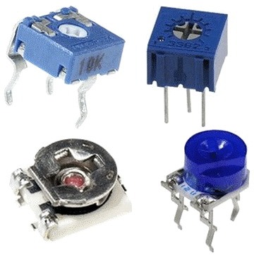
Let's take a look at the design of a thin film variable resistor brand SP1 . In the figure you see a real variable resistor, the resistance of which is 1 MΩ (1,000,000 ohms).

And here is its internal structure (protective cover removed). The main structural parts are also shown in the figure.

The fourth pin visible in the first image is the metal cover pin which serves as an electrical shield and is usually connected to ground (GND).
The tuning resistor has a similar design. Here take a look. In the photo, a tuning resistor SP3-27b (150 kOhm).

Resistance adjustment is carried out with an adjusting screwdriver. For this, a groove is provided in the design of the resistor.
Now that we have dealt with the arrangement of variables and trimmers, let's find out how they are indicated on the circuit diagram.
Designation of variables and trimmers on circuit diagrams.
The usual image of a variable resistor in a circuit diagram.

As you can see, it consists of the designation of a conventional constant resistor and a "tap" - an arrow. An arrow with a tap symbolizes the middle contact, which we move over the surface of a high-resistance wire wound on a frame or a thin-film coating.
Next to the graphic image, the letter R is placed with a serial number in the diagram. The nominal resistance is also indicated next to it (for example, 100k - 100 kOhm).
If a variable resistor is included in the circuit with a rheostat (the movable middle terminal is connected to one of the extreme ones), then it can be indicated on the diagram with two terminals (in the image it is R2). On foreign circuits, a variable resistor is indicated not by a rectangle, but by a zigzag line. In the picture it is R3.
A variable resistor combined with a power switch.

Used in inexpensive portable equipment. The variable resistor itself, as a rule, is used in the sound volume control circuit, and since it is physically (but not electrically!) Combined with the switch, when you turn the knob, you can turn on the device and immediately adjust the sound volume. Prior to the widespread adoption of digital volume control, such combined resistors were widely used in portable radios.
In the photo - an adjusting resistor with a switch SP3-3bM .

The photo clearly shows the design of the switch, which closes its contacts when the dial is turned. It was often used in Soviet-made audio equipment (for example, in intercoms, radios, etc.).
Also in electronics, double or combined variable resistors are used. They have a movable contact structurally integrated, and by moving it you can change the resistance of two or more variable resistors at the same time.
Such resistors are often used in analog audio equipment as a stereo balance control or one of the multiband equalizer resistors. The number of dual resistors in a high-end equalizer can be up to 20.
The first square shows the designation of a double variable resistor (R1.1; R1.2), which is often used in stereo equipment. The second shows a conditional image on the circuit of a quad variable resistor. Pay attention to the lettering (R1.1; R1.2; R1.3; R1.4).

On circuit diagrams combined resistors are denoted using a connecting dotted line. This indicates that their moving contacts are mechanically combined on the shaft of one knob-regulator.
Designation of a tuning resistor.

The tuning resistor in the diagram is designated similarly to a variable, with one exception - it does not have an arrow. This tells us that the resistance is adjusted either once when setting up the electronic circuit, or very rarely during maintenance work.
Types of variables and trimmers.
In order to have an idea about the whole variety of variables and trimmers, let's get acquainted with the photographs.
Non-separable variable resistor.
The usual variable resistor of wide application. Well visible type: SP4 - 1 , power 0.25 watts, resistance 100 kOhm.

The resistor from below is filled with epoxy compound, that is, it is non-separable and cannot be repaired. This type is very reliable, as it was produced for defense equipment.
These are trim resistors. SP3-16b . Resistors SP3-16b are designed for perpendicular installation on printed circuit board, and their power is 0.125 watts. They have a linear (A) functional characteristic. As you can see, their design is very solid and reliable.

Single-turn non-wire trimmer resistors.
A small-sized tuning resistor that is soldered directly into the printed circuit board of household equipment. It has very small dimensions and on some boards up to a dozen of its kind are soldered.
The photo below shows the trimmer resistors. SP3-19a (right) with a power of 0.5 watts. The material of the resistive layer is cermet.

Lacquer film resistors SP3-38 . Their device is very primitive.

Since its case is open, dust settles on the surface, moisture condenses, which affects the reliability of such a product. The conductor material is cermet, and the power is low - about 0.125 watts.
Adjustment of such resistors is carried out with a dielectric screwdriver to avoid a short circuit. They are fairly easy to find in consumer electronics.
Resistors RP1-302 (pictured right) and RP1-63 (left).

To adjust the resistance of the RP1-63 resistors, a special screwdriver may be required. If you look closely, the screwdriver slot has a hexagonal shape. Unlike SP3-38, such resistors have a protected housing. This has a positive effect on their reliability.
Powerful wire-wound trimmers.
Shown here is a powerful 3 watt wire wound resistor. SP5-50MA .

Its body is made spacious so that the conductive wire layer has an air flow for cooling. If you turn the resistor over, you can see in detail its device, including the insulating bar on which the high-resistance conductor is wound.

High voltage control resistors.
A fairly rare instance of a tuning resistor ( NR1-9A ). Not so long ago, they were in all kinescope TVs and were tied into a high voltage adjustment circuit. Its resistance is 68 MΩ. (In fact, I pulled it out of the TV to take a picture and show it to you).

HP1-9A itself is a set of cermet resistors. Its operating voltage 8500 V(this is 8.5 kilovolts !!!), and the maximum operating voltage is already 15 kV! Rated power - 4 W. Why is the HP1-9A control resistor called a set of resistors? Yes, because it consists of several. His internal structure corresponds to a circuit of 3 individual resistors.
In modern kinescope TVs, they are built directly into the TDKS (Diode Cascade Linear Transformer).
Sliding resistors are often used in analog controlled audio equipment. They are also called slider . They were widely used in electronic devices to adjust brightness, contrast, volume, tone, etc. Here is a look at their design.

The photo below shows a sliding variable resistor. SP3-23a . From the marking it follows that its power is 0.5 W, and the functional characteristic corresponds to a linear relationship (letter A). Resistance - 1 kOhm.

As well as variable resistors with a circular slide system, sliders can be doubled, for example, a resistor SP3-23b (the bottom one in the first photo). It consists of two variable resistors with a common moving contact.
Trimmer multi-turn resistors.
Very often, especially in special equipment, very convenient and at one time completely scarce wire-wound multi-turn tuning resistors were used.
The conclusions were also rigid for soldering into ready-made sockets, or made of flexible MGTF wire so that they could be soldered to any point on the board. From zero to maximum resistance, the adjusting screw for a screwdriver had to be turned exactly 40 times. This achieved a very high accuracy in setting the circuit parameters.

The photo shows a multi-turn trimmer SP5-2A . The change in resistance is made by circular movement of the movable contact system through the worm pair. For 40 full turns, you can change its resistance from minimal to maximum value. Resistors SP5-2A are used in DC and alternating current, and are designed for a power of 0.5 - 1 W (depending on the modification). Wear resistance - from 100 to 200 cycles. The functional characteristic is linear (A).
More full information for resistors of domestic production can be obtained from the reference book "Resistors" edited by I.I. Chetvertkov and V.M. Terekhov. It contains data for almost all resistors. You will find the guide.
Variable resistor repair.
Since variable resistors are an electromechanical product, they begin to deteriorate over time. Due to the wear of the conductive layer and the weakening of the pressure of the sliding contact, they begin to work poorly, the so-called "rustle" appears.
In most cases, it makes no sense to restore a faulty variable resistor, but there are exceptions. For example, the one you need to replace may simply not be at hand, or it may be very rare. So in some mixing consoles, quite rare and unique samples are used. It is difficult to find a replacement for them.
In this case, you can restore the correct operation of the variable resistor using a regular pencil. The lead of a pencil is made of graphite, a hard carbon. Therefore, you can carefully disassemble the variable resistor, bend the weakened sliding contact, and draw a pencil lead several times over the conductive layer. This will restore the conductive layer. It also does not hurt to lubricate the coating with silicone grease. Then we assemble the resistor back. Naturally, this method is only suitable for thin-film coated resistors.
To be honest, the simplest variable resistor can be made from a simple pencil, because its lead is made of carbon! And finally, let's figure out in our mind how this can be done.
Potentiometer is a device that most of us associate with the volume knob protruding from the radio. Today, in the era of digital circuits, the potentiometer is not used very often.
However, this device has a special charm and cannot be replaced where a smooth "analogue" adjustment is needed. For example, if you are playing game console with gamepad. The gamepad has analog knobs, which often consist of 2 potentiometers. One controls the horizontal axis and the other the vertical one. Thanks to these potentiometers, the game becomes more precise than on a conventional digital joystick.
The potentiometer is a variable resistor. A resistor is a radio element that makes it difficult for current to flow through it. It is used where it is necessary to reduce voltage or current.
An adjustable resistor or potentiometer serves the same purpose, except that it does not have a fixed resistance, but changes according to the user's demand. This is very convenient because everyone prefers different volume, brightness and other device characteristics that can be adjusted.

Today we can say that the potentiometer does not regulate functional characteristics device (this is done by the circuit itself with a digital display and buttons), but it serves to change its parameters, such as control in the game, deviation of the ailerons of a remotely controlled aircraft, rotation of a video surveillance camera, etc.
How does a potentiometer work?
A traditional potentiometer has an axis on which a knob is placed to change the resistance, and 3 outputs.
The two extreme terminals are connected by an electrically conductive material with constant resistance. In fact, this is a fixed resistor. The center pin of the potentiometer is connected to a moving contact that moves over the conductive material. As a result of changing the position of the movable contact, the resistance between the central terminal and the extreme terminals of the potentiometer also changes.
Thus, the potentiometer can change its resistance between the central contact and any of the extreme contacts from 0 ohm to the maximum value indicated on the case.
Schematically, a potentiometer can be represented as two fixed resistors:

In the voltage divider, the extreme terminals of the resistors are connected between the Vcc supply and the ground GND. And the middle pin with GND creates a new lower voltage.
Uout = Uin*R2/(R1+R2)
If we have a resistor with a maximum resistance of 10 kOhm and turn its knob to the middle position, then we will get 2 resistors with a value of 5 kOhm. By applying a voltage of 5 volts to the input, at the output of the divider we get the voltage:
Uout = Uin * R2/(R1+R2) = 5*5000/(5000+5000) = 5*5/10 = 5*1/2 = 2.5V
The output voltage turned out to be equal to half the input voltage.
But what happens if we turn the knob so that the center pin connects to the Vcc pin?
Uout = Uin*R2/(R1+R2) = 5*10000/(0+10000) = 5*10000/10000 = 5*1 = 5V
Since the resistance of the resistor R1 has decreased to 0 ohms, and the resistance of R2 has increased to 10 kOhm, we got the maximum output voltage at the output.
What happens if we turn the handle all the way in the opposite direction?
Uout \u003d Uin * R2 / (R1 + R2) \u003d 5 * 0 / (10000 0) \u003d 5 * 0 \u003d 0V
In this case, the resistance R1 will have a maximum resistance of 10 kOhm, and the resistance R2 will drop to 0. In fact, there will be no voltage at the output.


